TCP Coilover 2
|
|
TCP Coilover 2 |
 |
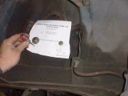 11) We recommend lowering the mounting location of the upper arm 1" for an improved negative camber curve. A template is included in the kit to make this easier. |
 12) Once the holes have been drilled mount the new upper control arm in the lowered mounting location. |
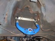
 13) Next, bolt the lower control arm into place. For 1967 and later Mustangs a eccentric eliminator plate is included in the kit to keep the lower arm in alignment. |
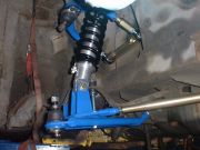
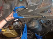 14) The new adjustable strut rod is then mounted to the frame. We have designed the strut rod plate as the lower mount for the coilover shock. |
 15) The strut rod has fixed bolts that are bolted through the lower control arm. |
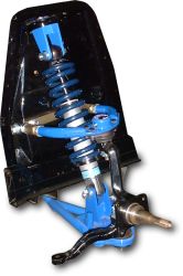
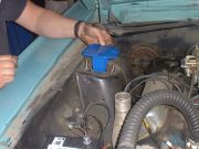 16) The new upper shock mount is installed on the shock tower using the factory holes. The stock export brace can then be bolted on top of the upper mount. |
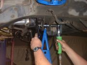
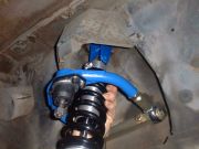 17) Installing the coilover shock is a snap. No need for special tools or even breaking a sweat. Slide the bolt through and tighten. |
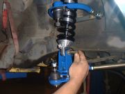 18) The lower end of the shock installs just as easily as the top mount. |
 19) Now that the new suspension components are in place, we are ready to bolt up the spindle and brakes. |
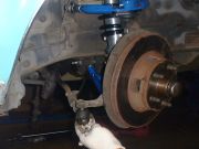 20) Reconnect the outer tie rod to the steering arm then check to make sure everything is torqued to its specified value.
|
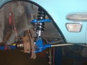 21) A trip to the alignment shop is in order before we find out what the new suspension system can really do. |